
Fastenings
Application
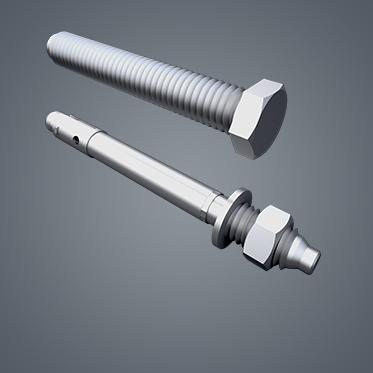
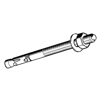
Anchor for push-through mounting in M&E services and plant construction in concrete tensile zones. This anchor combines high permissible loads with close edge and centre distances.
Suitable for anchoring in cracked and non-cracked concrete - fixation of pipelines, channels, brackets, etc. in closed rooms - except for damp locations.
- No special drill required. Bore dia = thread size
- Simple and quick mounting due to its push-through concept
- Drive-in hammer zone for preventing any thread damage
Scope of delivery
Supplied with washer and hexagon nut.
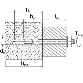
Installation
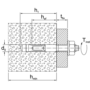
| 1. | Drill bore hole according to the minimum bore hole depth perpendicularly to the surface. |
| 2. | Remove dirt from hole. |
| 3. | Drive the anchor into concrete up to its embedment mark. |
| 4. | Immediately resilient after tightening with the torque wrench Tinst indicated in the table below. Advices of the mounting instruction are to be respected! |
Technical Data
Standard anchoring depth:
| Anchor size | M8 | M10 | M12 | M16 |
|---|---|---|---|---|
| Perm. load 1) tension C20/25 2) [kN] | 2.4 | 4.3 | 7.6 | 11.9 |
| C25/30 2) [kN] | 2.7 | 4.8 | 8.5 | 13.3 |
| C30/37 2) [kN] | 2.9 | 5.2 | 9.3 | 14.6 |
| C40/50 2) [kN] | 3.4 | 6.1 | 10.8 | 16.8 |
| C50/60 2) [kN] | 3.8 | 6.8 | 12.0 | 18.8 |
| Perm. load 1) oblique ≥ C20/25 2) [kN] | 7.0 | 11.5 | 17.1 | 30.8 |
| Perm. bending moment 1) [Nm] | 13.1 | 26.9 | 46.9 | 123.4 |
| Min. thickness of component hmin ≥ [mm] | 100 | 120 | 140 | 170 |
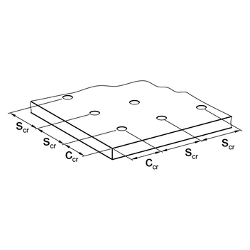
| (3 hef ) Charact. centre distance scr [mm] | 138 | 180 | 210 | 255 |
| (1,5 hef ) Charact. edge distance ccr [mm] | 69 | 90 | 105 | 127.5 |
| Min. centre distance s at/edge distance c ≥ [mm] | 40/70 | 45/70 | 60/100 | 60/100 |
| Min. edge distance c at/centre distance s ≥ [mm] | 40/80 | 45/90 | 60/140 | 60/180 |
| Effective anchoring depth hef [mm] | 46 | 60 | 70 | 85 |
| Nominal diameter of drill d0 [mm] | 8 | 10 | 12 | 16 |
| Depth of bore hole h1 ≥ [mm] | 60 | 75 | 90 | 110 |
| Anchoring torque Tinst [Nm] | 20 | 25 | 45 | 90 |
| Perm. load 3) for fire exposure | ||||
| Perm. load R30 perm. F [kN] | 1.25 | 2.25 | 4.0 | 6.25 |
| Perm. load R60 perm. F [kN] | 1.1 | 1.9 | 3.0 | 5.6 |
| Perm. load R90 perm. F [kN] | 0.8 | 1.4 | 2.4 | 4.4 |
| Perm. load R120 perm. F [kN] | 0.7 | 1.2 | 2.2 | 4.0 |
1) Loads for single anchors without influence of edge distances
2) Cracked concrete (option 1)
3) Edge/Centre distances in case of fire - respective approval is to be respected
Reduced anchoring depth:
| Anchor size | M8 | M10 | M12 | M16 |
|---|---|---|---|---|
| Perm. load 1) tension C20/25 2) [kN] | 2.4 | 3.6 | 5.8 | 8.6 |
| C25/30 2) [kN] | 2.7 | 4.0 | 6.5 | 9.6 |
| C30/37 2) [kN] | 2.9 | 4.4 | 7.1 | 10.5 |
| C40/50 2) [kN] | 3.4 | 5.1 | 8.2 | 12.2 |
| C50/60 2) [kN] | 3.8 | 5.6 | 9.2 | 13.6 |
| Perm. load 1) oblique ≥ C20/25 2) [kN] | 7.0 | 10.0 | 13.9 | 20.6 |
| Perm. bending moment 1) [Nm] | 13.1 | 26.9 | 46.9 | 123.4 |
| Min. thickness of component hmin ≥ [mm] | 80 | 80 | 100 | 140 |
| (3 hef ) Charact. centre distance scr [mm] | 105 | 120 | 150 | 195 |
| (1,5 hef ) Charact. edge distance ccr [mm] | 52.5 | 60 | 75 | 97.5 |
| Effective anchoring depth hef [mm] | 35 | 40 | 50 | 65 |
| Nominal diameter of drill d0 [mm] | 8 | 10 | 12 | 16 |
| Depth of bore hole h1 ≥ [mm] | 49 | 55 | 70 | 90 |
| Anchoring torque Tinst [Nm] | 20 | 25 | 45 | 90 |
| Perm. load 3) for fire exposure | ||||
| Perm. load R30 perm. F [kN] | 1.25 | 1.74 | 3.04 | 4.51 |
| Perm. load R60 perm. F [kN] | 1.1 | 1.74 | 3.0 | 4.51 |
| Perm. load R90 perm. F [kN] | 0.8 | 1.3 | 1.9 | 3.5 |
| Perm. load R120 perm. F [kN] | 0.6 | 1.0 | 1.3 | 2.5 |
1) Loads for single anchors without influence of edge distances
2) Cracked concrete (option 1)
Permissible loads according to EN 1992-4 without influence of centre and edge distances. Overall safety factor is taken into account ( YM und YF ). Values of the mentioned approval are valid and could be seen in the latest issue under www.sikla.com/service/downloads.
| Material: | Steel, galvanised |
Approvals / Compliance
Sikla Approval ETA-10/0259
FM-Approval for M10, M12, M16 only for Standard anchoring depth
VdS compliant for all sizes
Shock approval issued by the Federal Office for Civil Defence, Bern (Switzerland)
![]()

![]()
![]()

The types marked * are not part of the Seismic-Approval.
tfix = max. effective length [mm]
- ETA 10/0259 (application/pdf, 5.4 MB)
- FM - Sikla Anchors AN (application/pdf, 260.1 KB)
The types marked with * are not part of the Seismic approval.
1) Delivery date on request - goods are procured to order.
tfix = max. usable length [mm]
| Type | Thread connection |
Standard anchoring depth tfix |
Reduced anchoring depth tfix |
Total length [mm] |
W [kg] |
Quantity [pack] |
Part- No. |
|---|---|---|---|---|---|---|---|
| 8/6/60 s * | M8 | - | 6 | 60 | 0.03 | 100 | 114134 |
| 8/10/21/75 | M8 | 10 | 21 | 75 | 0.03 | 100 | 114135 |
| 8/30/41/95 | M8 | 30 | 41 | 95 | 0.04 | 100 | 114136 |
| 8/50/61/115 | M8 | 50 | 61 | 115 | 0.04 | 100 | 114137 |
| 8/100/111/165 1) | M8 | 100 | 111 | 165 | 0.06 | 50 | 114138 |
| 10/10/70 s * | M10 | - | 10 | 70 | 0.05 | 50 | 114139 |
| 10/10/30/90 | M10 | 10 | 30 | 90 | 0.06 | 50 | 114140 |
| 10/20/40/100 1) | M10 | 20 | 40 | 100 | 0.06 | 50 | 114141 |
| 10/30/50/110 | M10 | 30 | 50 | 110 | 0.07 | 50 | 114142 |
| 10/50/70/130 | M10 | 50 | 70 | 130 | 0.08 | 50 | 114143 |
| 10/75/95/155 | M10 | 75 | 95 | 155 | 0.09 | 50 | 114144 |
| 10/100/120/180 1) | M10 | 100 | 120 | 180 | 0.10 | 50 | 114145 |
| 12/10/85 s * | M12 | - | 10 | 85 | 0.08 | 25 | 114146 |
| 12/15/35/110 | M12 | 15 | 35 | 110 | 0.10 | 25 | 114147 |
| 12/30/50/125 | M12 | 30 | 50 | 125 | 0.11 | 25 | 114148 |
| 12/50/70/145 | M12 | 50 | 70 | 145 | 0.13 | 25 | 114149 |
| 12/65/85/160 1) | M12 | 65 | 85 | 160 | 0.14 | 25 | 114150 |
| 12/85/105/180 | M12 | 85 | 105 | 180 | 0.15 | 25 | 114151 |
| 12/105/125/200 1) | M12 | 105 | 125 | 200 | 0.17 | 25 | 114152 |
| 12/160/255 * 1) | M12 | 160 | - | 255 | 0.18 | 20 | 114153 |
| 16/5/105 s * 1) | M16 | - | 5 | 105 | 0.17 | 20 | 114154 |
| 16/25/45/145 | M16 | 25 | 45 | 145 | 0.23 | 20 | 114155 |
| 16/50/70/170 1) | M16 | 50 | 70 | 170 | 0.26 | 20 | 114156 |
| 16/100/220 * 1) | M16 | 100 | - | 220 | 0.35 | 10 | 114157 |