
Fastenings
Application
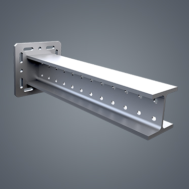
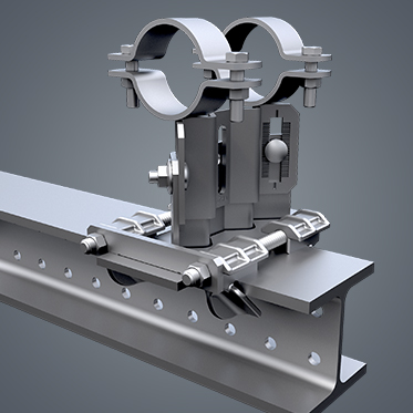
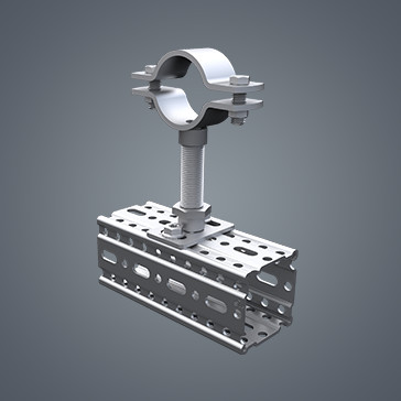
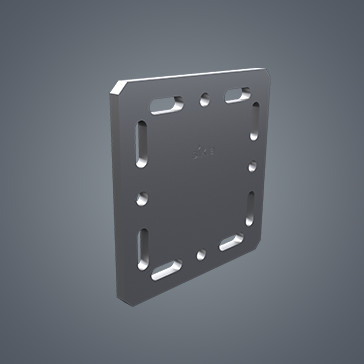
Suitable for quick and safe fixation of Sikla Channels or Mounting Plates to concrete and masonry ceilings or walls. To be applied in dry rooms not exposed to high corrosion resistance requirements.
- European Technical Assessment for anchoring in cracked and non-cracked concrete (Option 1)
- European Technical Assessment for multiple use for non-structural systems in concrete and precast pre-stressed hollow core slabs
- Approved for applications under seismic impact of category C1 and C2 (Types, diameters and anchoring depths are shown in the "type overview" and ETA-16/0655
- Also fixes into pressure-resistant natural stones and different solid bricks (not part of ETA approval / guideline)
- Flexible use for high or standard load performances due to 3 anchoring depths
- Small edge and axial distance due to low expansion pressure
- Low drillling effort
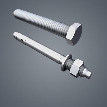
Installation
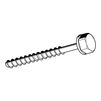
Screw in the bolt screw in pre-drilled hole. The special thread guarantees a mechanical form lock with the base material. Fine adjustment of depth is possible if the screwbolt is initially installed too deep.
Technical Data
Single fixing:
Extract from application conditions of ETA-16/0655
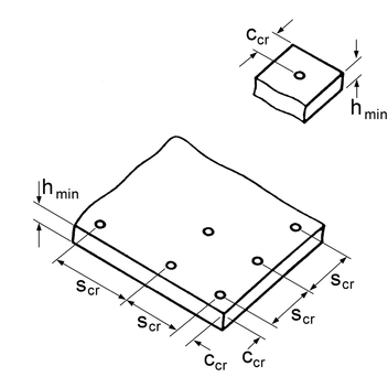
Permissible loads according to EN 1992-4 without influence of centre and edge distances. Overall safety factor is taken into account ( YM und YF ).
Diameter 6 mm
| Embedment depth 40 mm | Embedment depth 55 mm | |
|---|---|---|
| Drive | SW 13 | SW 13 |
| Nominal diameter of drill d0 [mm] | 6 | 6 |
| Depth of bore hole h1 [mm] | 45 | 60 |
| Approved loads cracked concrete | ||
| C20/25 [kN] | 1.0 | 1.9 |
| Approved loads non-cracked concrete | ||
| C20/25 [kN] | 1.9 | 4.3 |
| Minimum thickness of concrete slab hmin [mm] | 100 | 100 |
| Char. spacing scr,N | 93 | 132 |
| Char. edge distance ccr,N | 46.5 | 66 |
| Diameter of clearance hole in the fixture ≤ [mm] | 8 | 8 |
Diameter 8 mm
| Embedment depth 45 mm | Embedment depth 55 mm | Embedment depth 65 mm | |
|---|---|---|---|
| Drive | SW 13 | SW 13 | SW 13 |
| Nominal diameter of drill d0 [mm] | 8 | 8 | 8 |
| Depth of bore hole h1 [mm] | 55 | 65 | 75 |
| Approved loads cracked concrete | |||
| C20/25 [kN] | 2.4 | 4.3 | 5.7 |
| Approved loads non-cracked concrete | |||
| C20/25 [kN] | 3.6 | 5.7 | 7.6 |
| Minimum thickness of concrete slab hmin [mm] | 80 | 80 | 80 |
| Char. spacing scr,N | 105 | 129 | 156 |
| Char. edge distance ccr,N | 52.5 | 64.5 | 78 |
| Diameter of clearance hole in the fixture ≤ [mm] | 12 | 12 | 12 |
Diameter 10 mm
| Embedment depth 55 mm | Embedment depth 75 mm | Embedment depth 85 mm | |
|---|---|---|---|
| Drive | SW 15 | SW 15 | SW 15 |
| Nominal diameter of drill d0 [mm] | 10 | 10 | 10 |
| Depth of bore hole h1 [mm] | 65 | 85 | 95 |
| Approved loads cracked concrete | |||
| C20/25 [kN] | 4.3 | 7.6 | 9.2 |
| Approved loads non-cracked concrete | |||
| C20/25 [kN] | 5.7 | 9.5 | 12.4 |
| Minimum thickness of concrete slab hmin [mm] | 80 | 90 | 102 |
| Char. spacing scr,N | 129 | 180 | 204 |
| Char. edge distance ccr,N | 64.5 | 90 | 102 |
| Diameter of clearance hole in the fixture ≤ [mm] | 14 | 14 | 14 |
Diameter 12 mm
| Embedment depth 65 mm | Embedment depth 85 mm | Embedment depth 100 mm | |
|---|---|---|---|
| Drive | SW 17 | SW 17 | SW 17 |
| Nominal diameter of drill d0 [mm] | 12 | 12 | 12 |
| Depth of bore hole h1 [mm] | 75 | 95 | 110 |
| Approved loads cracked concrete | |||
| C20/25 [kN] | 5.7 | 9.0 | 11.7 |
| Approved loads non-cracked concrete | |||
| C20/25 [kN] | 7.6 | 12.8 | 16.8 |
| Minimum thickness of concrete slab hmin [mm] | 80 | 101 | 120 |
| Char. spacing scr,N | 150 | 201 | 240 |
| Char. edge distance ccr,N | 75 | 100.5 | 120 |
| Diameter of clearance hole in the fixture ≤ [mm] | 16 | 16 | 16 |
Multiple fixing:
Extract from application conditions of ETA-16/0656
For the multiple use for non-structural applications. Permissible loads according to EN 1992-4 without influence of centre and edge distances. The overall safety factor is taken into account ( YM und YF ).
The maximum permissible load per fixing point may be less than the permissible load of the anchor, depending on national regulations.
Diameter 6 mm
| Embedment depth 35 mm | Embedment depth 55 mm | |
|---|---|---|
| Drive | SW 13 | SW 13 |
| Nominal diameter of drill d0 [mm] | 6 | 6 |
| Depth of bore hole h1 [mm] | 40 | 60 |
| Approved loads cracked concrete | ||
| C20/25 [kN] | 1.4 | 3.6 |
| Approved loads non-cracked concrete | ||
| C20/25 [kN] | 1.4 | 3.6 |
| Minimum thickness of concrete slab hmin [mm] | 80 | 100 |
| Char. spacing scr,N | 81 | 132 |
| Char. edge distance ccr,N | 40.5 | 66 |
| Diameter of clearance hole in the fixture ≤ [mm] | 8 | 8 |
Further technical information (load capacities under fire exposure, appr. loads in further concrete classes and precast pre-stressed hollow core slabs) are shown in the following overview.
| Material: | Steel, electrogalvanized |
- Technical data Screwbolt TSM (application/pdf, 227.2 KB)
- Type overview Screwbolt TSM (application/pdf, 100.1 KB)
Approvals / Compliance
ETA-16/0655 and ETA-16/0656
![]()
![]()
![]()

![]()
- Screwbolt TSM - ETA 16/0655 (application/pdf, 2.0 MB)
- Screwbolt TSM - ETA 16/0656 (application/pdf, 1.8 MB)
- Screwbolt TSM (Single use) (application/pdf, 2.1 MB)
- Screwbolt TSM (Multiple use) (application/pdf, 564.5 KB)
* Only to be used as multiple fixing for non-load-bearing systems in concrete and prestressed concrete hollow plate ceilings.
1) Liefertermin auf Anfrage – Ware wird auftragsbezogen beschafft.
| Type | Length [mm] |
W [kg] |
Quantity [pack] |
Part- No. |
|---|---|---|---|---|
| 6 x 40 * | 40 | 0.02 | 100 | 115737 |
| 6 x 50 | 50 | 0.02 | 100 | 115720 |
| 6 x 60 | 60 | 0.02 | 100 | 115723 |
| 6 x 80 | 80 | 0.02 | 100 | 115738 |
| 6 x 100 1) | 100 | 0.03 | 100 | 115739 |
| 8 x 50 | 50 | 0.03 | 50 | 115731 |
| 8 x 60 | 60 | 0.04 | 50 | 115732 |
| 8 x 70 | 70 | 0.04 | 50 | 115734 |
| 8 x 80 | 80 | 0.04 | 50 | 115735 |
| 8 x 90 1) | 90 | 0.05 | 50 | 115736 |
| 8 x 100 1) | 100 | 0.05 | 50 | 115728 |
| 8 x 120 1) | 120 | 0.06 | 50 | 115729 |
| 8 x 140 1) | 140 | 0.07 | 50 | 115730 |
| 10 x 60 | 60 | 0.06 | 50 | 115740 |
| 10 x 70 | 70 | 0.06 | 50 | 115741 |
| 10 x 80 1) | 80 | 0.07 | 50 | 115743 |
| 10 x 90 1) | 90 | 0.07 | 50 | 115744 |
| 10 x 100 1) | 100 | 0.08 | 50 | 115745 |
| 10 x 140 1) | 140 | 0.11 | 50 | 115746 |
| 12 x 110 1) | 110 | 0.12 | 25 | 115747 |
| 12 x 130 | 130 | 0.13 | 25 | 115748 |
| 12 x 150 | 150 | 0.15 | 25 | 115749 |